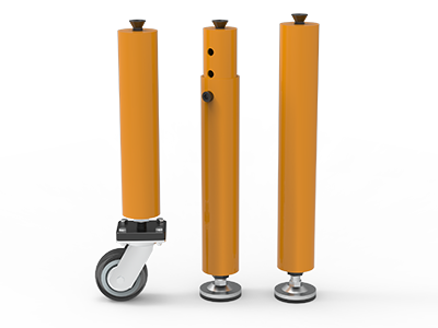
 Round Table Legs
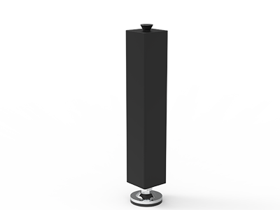 Square Table Legs
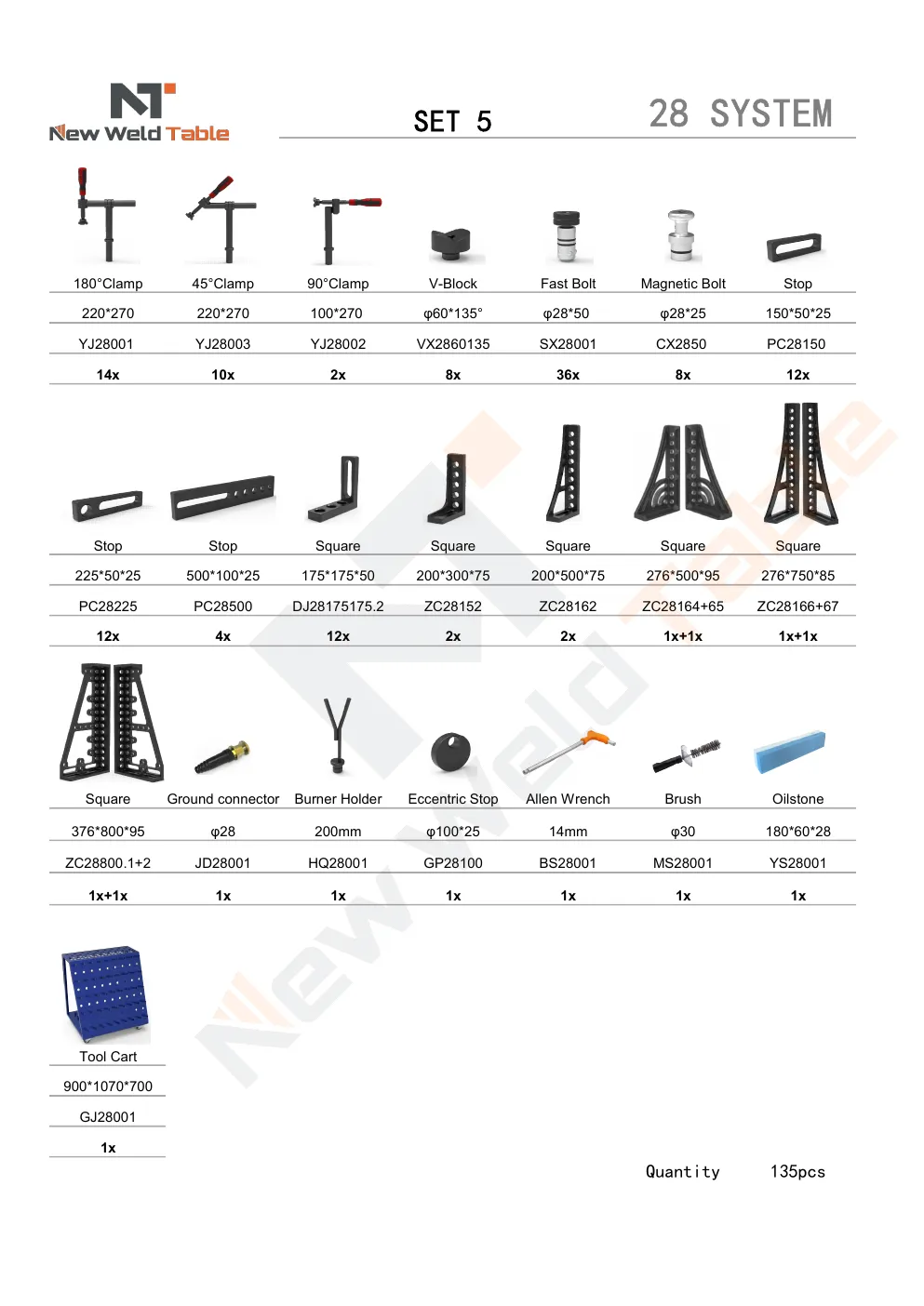
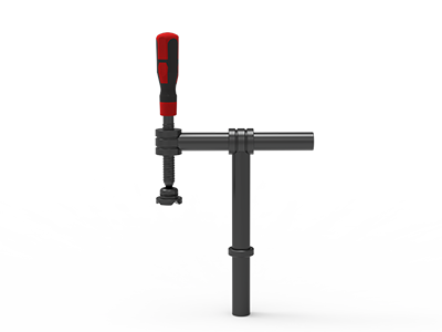 Clamp 180°
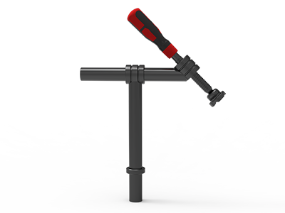 Clamps 45°
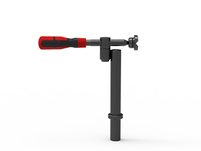 clamp 90°
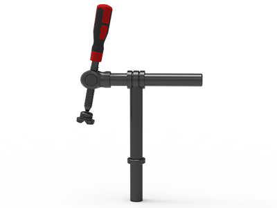 DRINK
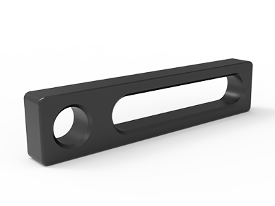 Stop
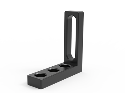 Angle Stop
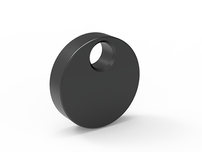 Eccentric Stop Ø 60
 Angle Alignment Template
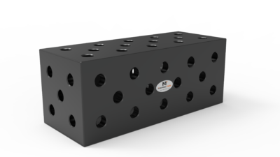 Square u-shape
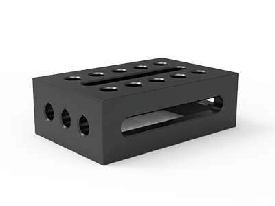 Support and clamping frame
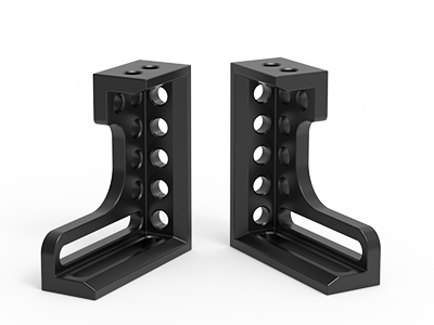 Angle support
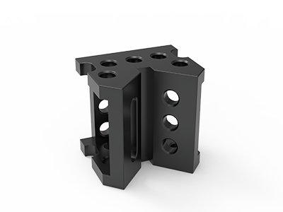 Corner Connection
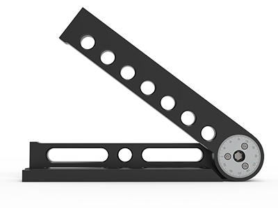 Universal angle clamping
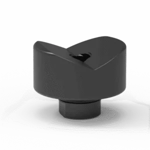 Prism with screwed-in collar
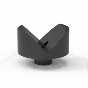 Prism with screwed-in collar
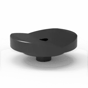 Prism with screwed-in collar
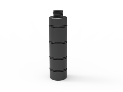 Prism Extension
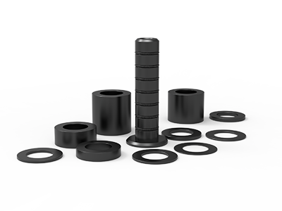 Set of Supports 11-piece set
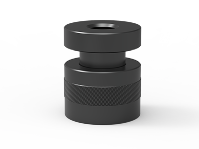 Screw Support Ø 80
 Shipping Bracket
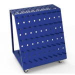 Tool Cart
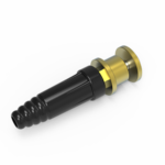 Ground Connection
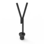 Welding torch holder
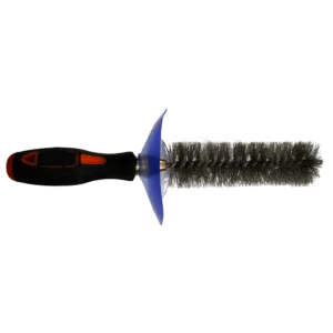 Brush with protecting cover
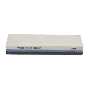 Oilstone
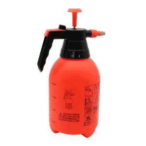 Pump Spray Bottle
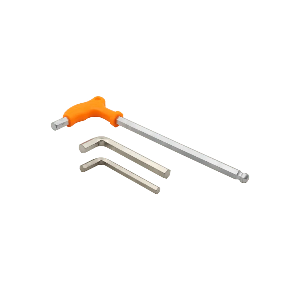 Allen Wrench
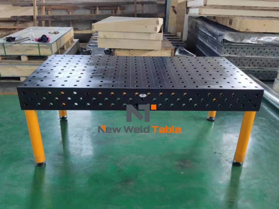
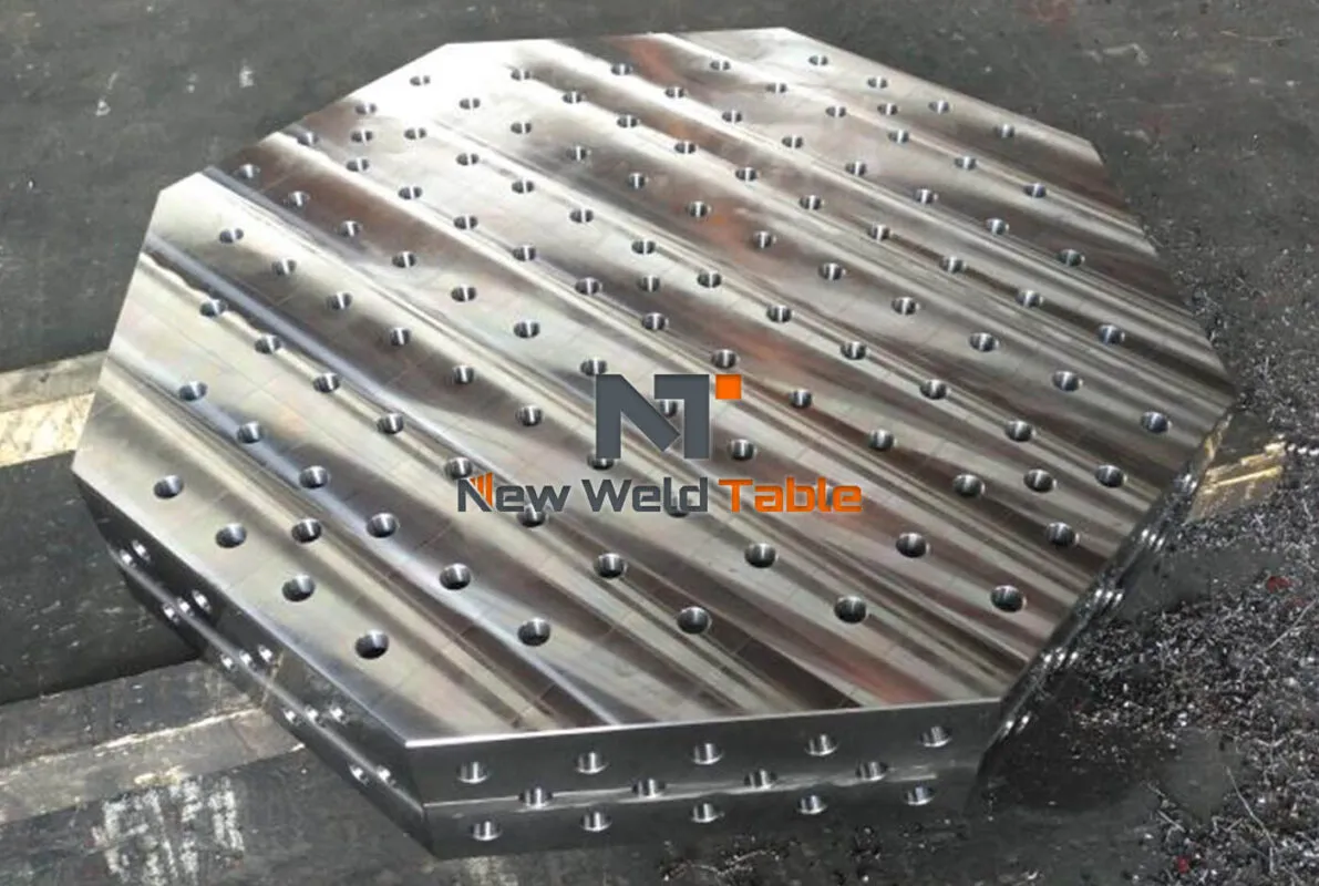
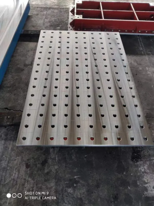
50 mm vs 100 mm Hole Spacing on 3D Welding Tables
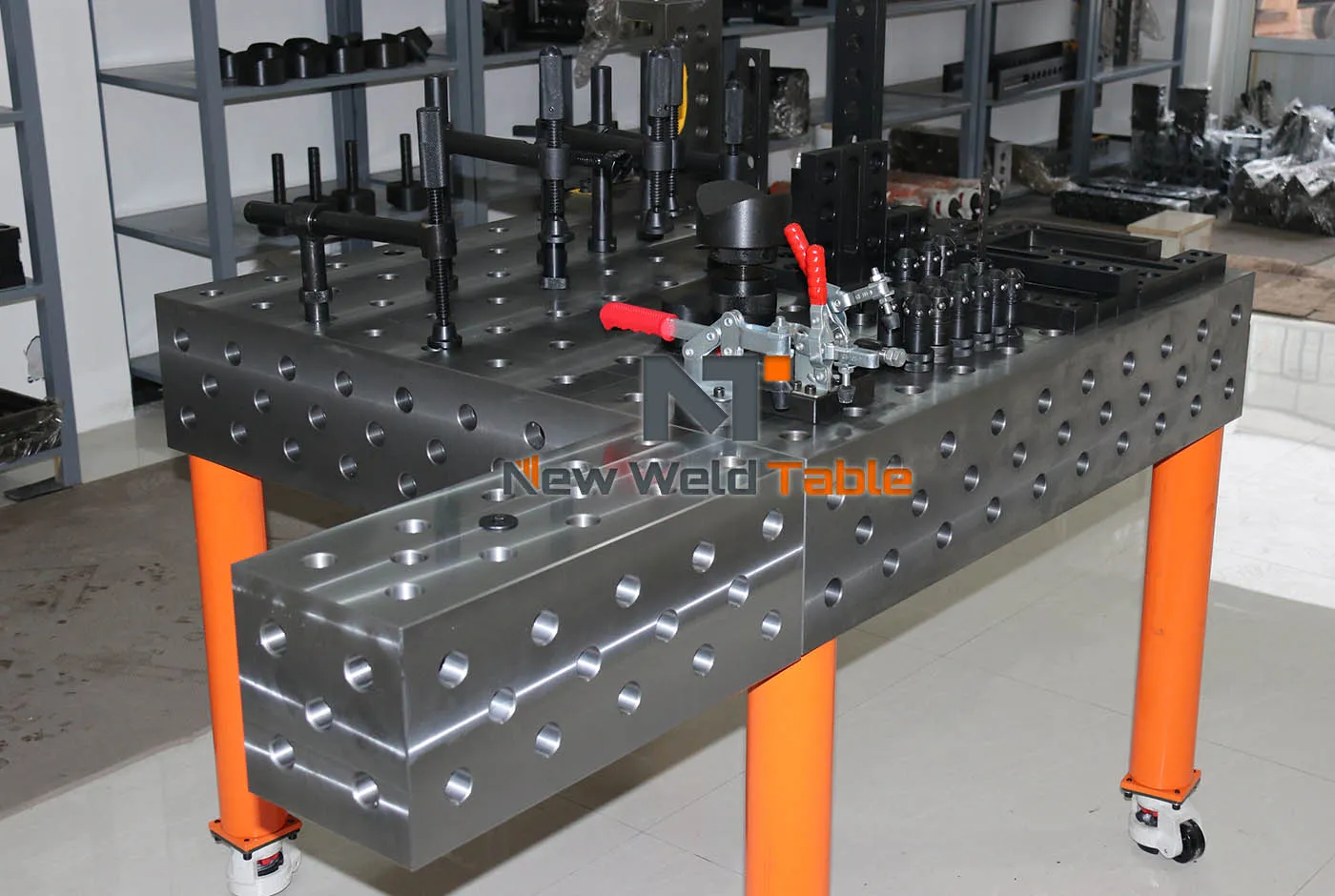
Choose 50 mm hole spacing when you regularly fixture small, irregular or frequently changing parts and need more clamping positions. Choose 100 mm spacing when your workpieces are larger, the fixture layout is simpler and you prefer fewer holes to machine and clean. Grid pitch is important, but it must be evaluated together with the D16 or D28 system, table size, tooling and required accuracy.
Hole spacing—also called grid pitch—is the center-to-center distance between adjacent bores on the working surface. It determines where bolts, clamps, stops and squares can be placed directly into the table. A smaller pitch creates a denser grid; a larger pitch creates a more open surface.
50 mm vs 100 mm grid: quick comparison
| Selection factor | 50 mm hole spacing | 100 mm hole spacing |
|---|---|---|
| Positioning options | More direct clamping positions | Fewer positions; tooling bridges larger intervals |
| Typical workpieces | Small frames, brackets, prototypes and mixed batches | Large frames, structural fabrications and repeat jobs |
| Fixture changes | Flexible for frequent layout changes | Efficient for stable, simpler layouts |
| Surface openness | Higher hole density | More uninterrupted surface between holes |
| Cleaning | More bores to inspect and clean | Fewer bores to maintain |
| Machining scope | More holes for the same table area | Fewer holes for the same table area |
| Best buying priority | Maximum positioning flexibility | Practical large-part fixturing |
What changes when grid pitch is reduced?
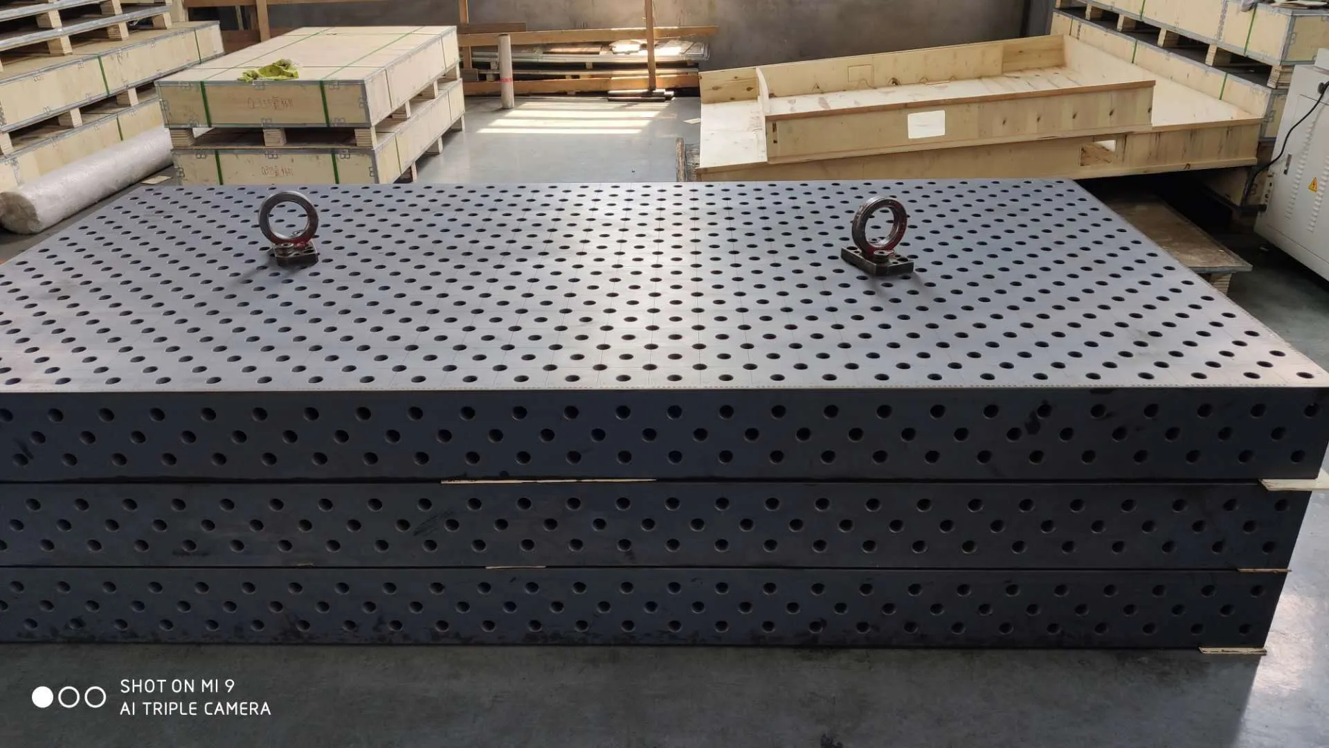
Reducing the pitch from 100 mm to 50 mm doubles the number of grid intervals in each direction. Across the same working area, that means the density of possible grid intersections increases by approximately four times. The exact number of holes depends on the edge offset and table design, but the practical result is clear: the operator gains more direct fixture locations.
More holes do not automatically make a table more accurate. Accuracy depends on bore diameter, center-distance tolerance, surface flatness, perpendicularity and the relationship between the top and side faces. Grid pitch describes layout density; it does not replace a dimensional specification.
When 50 mm hole spacing is the better choice
A 50 mm grid is valuable when fixture points must be moved in small increments. It suits workshops that handle prototypes, short production runs or many part families on one table. The denser grid reduces the number of situations where an operator needs an extra slotted plate or long stop simply to reach the required location.
- Small welded frames and brackets with closely spaced features.
- Prototype work where fixture locations change frequently.
- Mixed-batch production using one table for many assemblies.
- Components with limited access around the weld joint.
- Applications requiring several independent stops or clamps in a compact area.
The trade-off is greater hole quantity. This may increase machining time and gives the operator more bores to protect from spatter and debris. The benefit is justified only when the additional positions are actually used.
When 100 mm hole spacing is the better choice
A 100 mm grid is often practical for medium and large fabrications where clamps and squares can span wider distances. Structural frames, machinery bases, doors, railings and long weldments normally rely on fewer but stronger fixture points distributed across a larger surface.
- Large frames with long straight members.
- Heavy components using D28 clamps and squares.
- Repeat jobs with a stable fixture layout.
- Workshops prioritizing a more open, easier-to-clean surface.
- Projects where extension blocks and large tooling provide intermediate reach.
A 100 mm grid does not prevent precise positioning. Stops, slotted tools, eccentric stops and adjustable clamps can create intermediate locations. The correct question is whether the tooling package gives the operator enough reach without making setup complicated.
Does D16 always use 50 mm and D28 always use 100 mm?
No. D16 and D28 identify the nominal tooling system, while 50 mm and 100 mm describe grid spacing. Many compact D16 tables use a 50 mm grid and many heavy-duty D28 tables use a 100 mm grid, but these pairings are not universal. Manufacturers may offer alternative or mixed patterns, so the approved drawing must state both bore size and pitch.
System selection should start with the workpiece weight, required clamping force and accessory size. Read our D16 vs D28 welding table guide before using hole spacing as the final deciding factor.
How hole spacing affects fixture design
Fixture design is a reach problem. Every clamp, stop and square has a working envelope. A denser grid gives the base of the tool more possible locations; longer or slotted tooling extends the working envelope from a wider grid. Both methods can position the part, but they affect setup speed, tooling count and operator convenience differently.
Before ordering, place the workpiece drawing over the proposed grid. Mark the required datum points, clamp directions, weld access and part-removal path. This simple layout exercise shows whether the standard pitch works or whether additional holes, slots or custom tooling are needed.
Five questions that determine the right pitch
- What is the smallest repeated distance between fixture points? If many positions fall between a 100 mm grid, a 50 mm pattern may reduce setup time.
- How often does the product change? High-mix production benefits more from dense positioning than a dedicated repeat fixture.
- How heavy are the parts and tools? Heavy fabrication may prioritize D28 tooling capacity over maximum hole density.
- Can slotted or adjustable tooling reach the intermediate positions? If yes, a wider grid may remain flexible enough.
- How much cleaning and maintenance is acceptable? More bores provide more options but require more attention.
Do not confuse spacing with tolerance
Two tables can both use a 100 mm grid and still perform very differently. The purchasing specification should separately define the nominal pitch, allowable center-distance deviation, hole diameter, surface flatness and side-face relationship. Ask the manufacturer to explain the inspection method and provide results for the finished table.
Our guide to 3D welding table grid tolerance explains why a nominal layout alone does not guarantee repeatable fixturing.
How to specify hole spacing in an RFQ
Do not write only “D28 welding table.” Give the supplier enough information to quote the same technical scope:
- Working surface length and width.
- Nominal bore system: D16 or D28.
- Grid pitch in both directions: for example, 50 × 50 mm or 100 × 100 mm.
- Edge offset to the first row of holes.
- Required side-face hole pattern.
- Flatness and grid-position acceptance criteria.
- Material and surface treatment.
- Workpiece size, weight and representative drawings.
- Required clamps, stops, squares, supports and extensions.
If you are still deciding the working area, use our guide on choosing the right 3D welding table size. Table dimensions and grid pitch should be selected together.
Frequently asked questions
Is 50 mm hole spacing more accurate than 100 mm spacing?
No. A 50 mm grid provides more fixture locations, but accuracy depends on machining tolerance, hole diameter, surface flatness and inspection. Pitch and precision must be specified separately.
Does a 50 mm grid cost more?
It can require more machining because the same surface contains more bores. The final price also depends on table size, material, construction, heat treatment, surface treatment and inspection requirements. Compare complete quotations rather than assuming the grid is the only cost driver.
Can I order a custom or mixed hole pattern?
Yes, many manufacturers can machine custom patterns. Provide a dimensioned drawing and confirm tooling access, edge distances and inspection criteria. A custom pattern is worthwhile when it solves a repeated production requirement, not merely to add unused holes.
Need help choosing a grid pattern?
Send NewWeldTable your workpiece drawing, typical part size, weight and required table dimensions. We can recommend a D16 or D28 system, suitable hole spacing and the tooling needed for your production layout.