
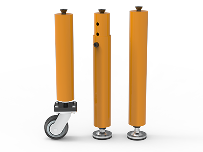
 Round Table Legs
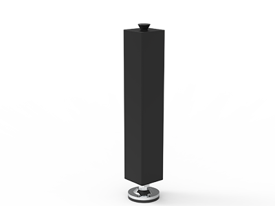 Square Table Legs
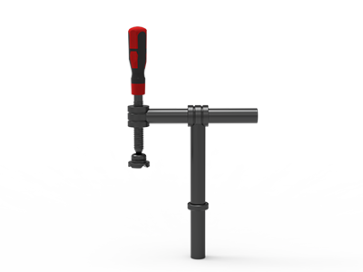 Clamp 180°
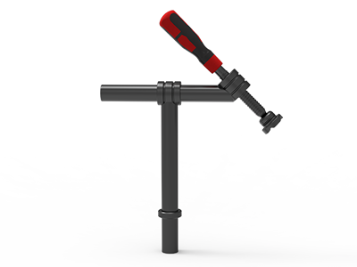 Clamps 45°
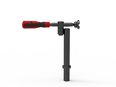 clamp 90°
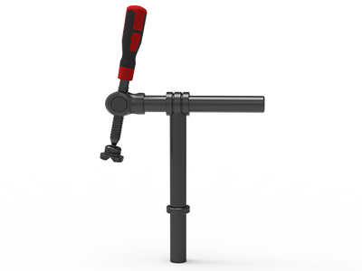 DRINK
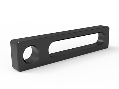 Stop
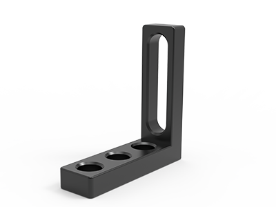 Angle Stop
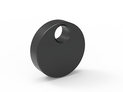 Eccentric Stop Ø 60
 Angle Alignment Template
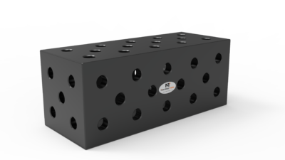 Square u-shape
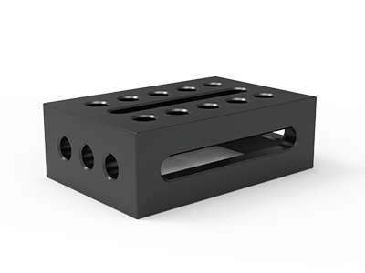 Support and clamping frame
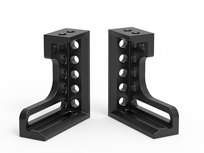 Angle support
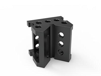 Corner Connection
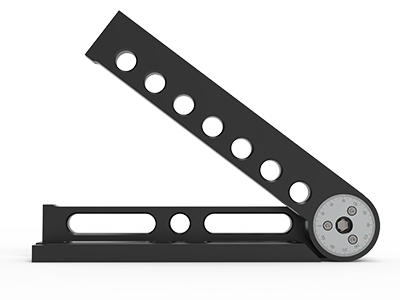 Universal angle clamping
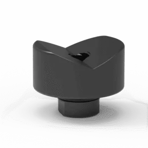 Prism with screwed-in collar
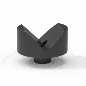 Prism with screwed-in collar
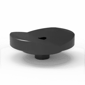 Prism with screwed-in collar
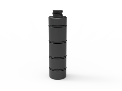 Prism Extension
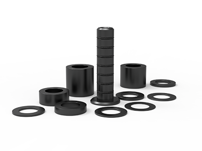 Set of Supports 11-piece set
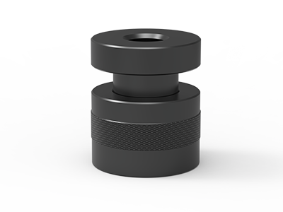 Screw Support Ø 80
 Shipping Bracket
 Tool Cart
 Ground Connection
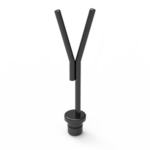 Welding torch holder
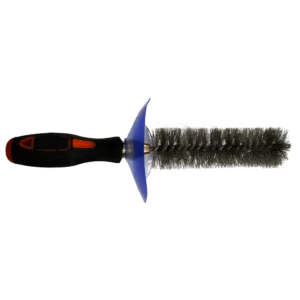 Brush with protecting cover
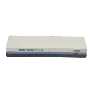 Oilstone
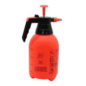 Pump Spray Bottle
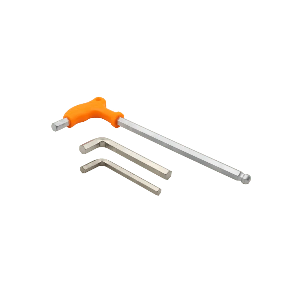 Allen Wrench
Welding Fixture Setup for Rectangular Tube Frames
Workshop guide · Rectangular tube frames
A repeatable rectangular frame starts with a clear datum, supported members and clamps that hold the assembly without forcing it into shape. A good welding fixture setup also leaves room for the torch, allows the finished frame to come out, and includes inspection after the clamps are released.
This guide follows an illustrative 1,200 × 800 mm mild-steel tube frame from dry fit to first-piece inspection on a modular 3D welding table. The dimensions explain the method; they are not a customer case study or a guaranteed production tolerance.
Start with the drawing: identify the dimensions and reference surfaces that matter after welding. A square-looking frame is not necessarily a conforming frame, and a part that measures correctly while clamped has not yet passed final inspection.
1. Define the frame before choosing the tooling
For the example, assume a rectangular frame made from 50 × 50 × 3 mm square tube with mitred corners. Confirm whether the drawing dimensions refer to outside faces, inside openings or tube centrelines. Those references produce different stop positions. A butt-jointed design would also need a different cut list and joint arrangement.
Put the following information on a one-page setup sheet:
- Drawing revision, tube size, material and corner-joint detail.
- Required length, width, squareness, flatness and their acceptance limits.
- Reference faces, inspection points and any functional mounting features.
- Specified welds and the applicable welding procedure.
- Whether acceptance applies in the free state or in a defined inspection fixture.
Do not assume that a table’s published flatness becomes the frame’s finished tolerance. Cut accuracy, tube straightness, seating, fixture clearance, welding and measurement all affect the result.
2. Establish datums, then add support
Locators establish position; clamps retain it. The familiar 3-2-1 locating concept uses a primary plane, a secondary side reference and a final end reference. Carr Lane’s locating and clamping principles provide a useful explanation of this distinction.
A welded frame is an assembly of separate, potentially flexible members, so do not treat six contacts as a complete fixture recipe. Each loose tube needs support and location before tacking. For this example, designate the bottom support plane as A, the outside face of one long rail as B, and the adjacent end reference as C.
- Plane A: use clean, verified support surfaces at the planned working height.
- Reference B: position two separated stops along the chosen long rail.
- Reference C: position an end stop from the same drawing reference.
- Remaining members: add adjustable locators for the opposite rail and cross members.
Bring supplementary supports into contact without lifting the tube off the primary plane. Check for burrs, spatter and rounded tube edges where tooling contacts the workpiece. Mark the reference rail so the next operator loads the same face against the same stops.
3. Match the table and accessories to the layout
Draw the frame and tooling footprint before choosing a table size. A 1,200 × 800 mm frame needs room beyond its outline for stop bases, clamp handles and access. If using a 2,000 × 1,000 mm table as a layout candidate, the nominal spare space is only 200 mm across the width before tooling is placed. Verify the actual arrangement rather than assuming it fits comfortably.
D16 and D28 describe nominal hole systems, not a complete load rating. Confirm bore fit, bolt engagement, tooling dimensions and the manufacturer’s capacity information. Our D16 vs D28 selection guide covers the broader system choice.
Grid pitch determines available base positions; adjustable tooling establishes intermediate locations. Use the 50 mm vs 100 mm hole-spacing comparison when checking reach. Whatever the table material or surface treatment, inspect the actual contact surfaces before setup.
| Component | Job in the fixture | Check before use |
|---|---|---|
| Stops and squares | Establish rail and end references | Contact face, adjustment range and secure mounting |
| Supports or spacers | Hold members at the required height | Equal reference height and clearance below joints |
| Hold-down clamps | Keep tubes seated | Reach, pad contact and support beneath the load |
| Lateral clamps | Seat members against stops | Force direction and access to the joint |
| System bolts | Secure modular tooling | Compatible bore and engagement length |
4. Dry-fit and measure before applying full restraint
Load the tubes, seat them gently and check the joint gaps against the drawing or procedure. If a corner closes only when a clamp bends a rail, investigate the cut length, mitre angle, straightness or stop setting. Increasing force can hide the problem until unloading.
Measure overall length and width at defined locations, then both diagonals between repeatable corner references. For an ideal 1,200 × 800 mm rectangle, the nominal outside-corner diagonal is:
√(1,200² + 800²) ≈ 1,442.2 mm
This is a geometric reference, not an acceptance limit. Mitres, edge radii and measurement access can change where the instrument actually touches.
Matching diagonals alone do not prove that every side dimension, corner angle or out-of-plane condition is correct. Check those separately. Use instruments with suitable resolution and repeatability for the drawing limits; a quick tape check may help with setup but may not establish final conformity.
5. Clamp with a clear force path
Apply clamp force toward the locators and supported areas. On a tube, place the pad where it has stable contact and the load can be supported. Avoid pressing a thin wall over a gap. Tighten progressively while watching whether the member lifts, twists or moves away from another reference.
Before striking an arc, move the unpowered torch around each planned weld. Check nozzle clearance, approach angle, clamp-handle access and the removal route. A removable end stop can be useful when a closed frame would otherwise become trapped in the fixture.
Restraint does not eliminate shrinkage. TWI explains that restraint can introduce residual stress and that movement may occur when it is removed. See its guidance on distortion prevention using restraint. Fixture design and the welding procedure must work together.
6. Validate the tack and weld sequence on a first piece
Identify the corners on the setup sheet and record the approved tack and weld sequence. Do not prescribe a universal tack length, current or weld order from frame size alone: joint design, tube wall thickness, process and weld requirements change the choice.
Recheck seating, length, width and diagonals after tacking. TWI’s fabrication guidance on distortion control notes that tack number, size and spacing affect joint-gap control. Tacks incorporated into the final weld must meet the applicable procedure requirements.
Complete welding under the selected procedure, then inspect at the specified temperature and restraint condition. For free-state acceptance, record the frame after controlled unclamping. If dimensions change substantially, investigate the process before copying the fixture settings to the whole batch.
7. Diagnose errors before changing the stops
| Symptom | What to investigate | Practical first check |
|---|---|---|
| Correct while clamped; wrong after release | Forced fit, weld shrinkage or restraint effects | Compare dry-fit, tacked and released measurements |
| One corner rises during tightening | Support height or clamp position | Release that clamp and check seating |
| Diagonal difference varies between parts | Cut variation, seating or loose tooling | Inspect incoming tubes and locator security |
| Same offset on successive frames | Reference interpretation or stop position | Verify the setup against the drawing datums |
| Finished frame is difficult to remove | Trapped geometry or blocked extraction | Review removable stops and unloading clearance |
Change one relevant setting at a time and record the result. Moving stops to compensate for one defective tube can transfer that error to the next good part.
8. Save a setup that another operator can repeat
Record the table orientation, grid coordinates, tooling IDs, adjustable stop offsets, support heights, loading order and inspection points. Include the drawing revision and approved sequence. A layout sketch helps, but dimensions and reference labels make the setup reproducible.
Before releasing the batch, confirm:
- The first piece meets drawing limits under the required inspection conditions.
- Clamp positions allow every weld and safe removal of the frame.
- Tooling remains secure and contact surfaces are clean.
- The next piece seats without forcing and reproduces the intended setup.
Keep this record with the job. It gives future repeat orders a documented starting point and helps distinguish fixture changes from material or welding changes.
Common questions about frame fixturing
How many clamps does a rectangular frame need?
There is no reliable count based only on four corners. Each loose member must remain seated and located without obstructing welds. Validate the number and positions on the actual assembly.
Can a precision welding table guarantee a square frame?
No. It provides a reference for tooling. Finished geometry also depends on component preparation, fixture arrangement, welding and inspection after release.
Plan the tooling around your frame drawing
Send your drawing, tube section, maximum workpiece size and weight, batch quantity and required tolerances. Add your preferred hole system and delivery destination so the table, tooling and shipping scope can be considered together. Explore our welding tables for machinery frames for application context.
Request a table and tooling quotationTechnical references are linked beside the relevant principles. The worked dimensions and setup worksheet are illustrative; acceptance limits come from your drawing and production requirements.