
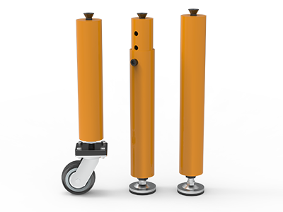
 Round Table Legs
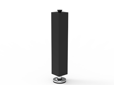 Square Table Legs
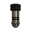
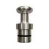
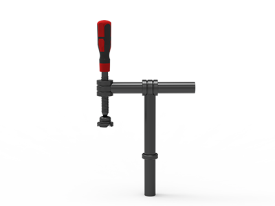 Clamp 180°
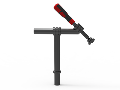 Clamps 45°
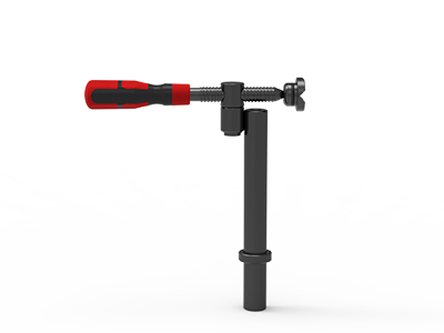 clamp 90°
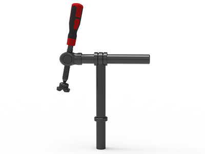 DRINK
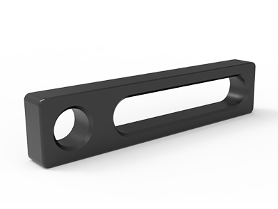 Stop
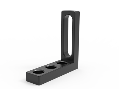 Angle Stop
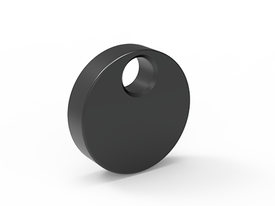 Eccentric Stop Ø 60
 Angle Alignment Template
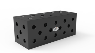 Square u-shape
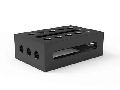 Support and clamping frame
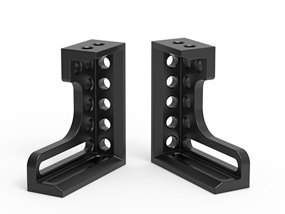 Angle support
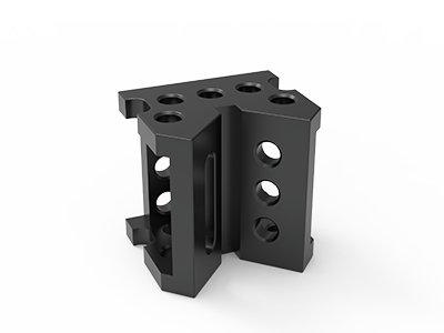 Corner Connection
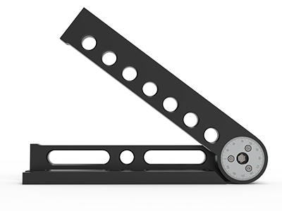 Universal angle clamping
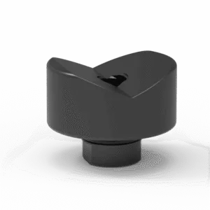 Prism with screwed-in collar
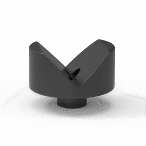 Prism with screwed-in collar
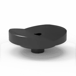 Prism with screwed-in collar
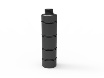 Prism Extension
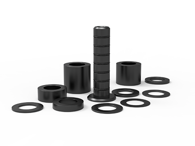 Set of Supports 11-piece set
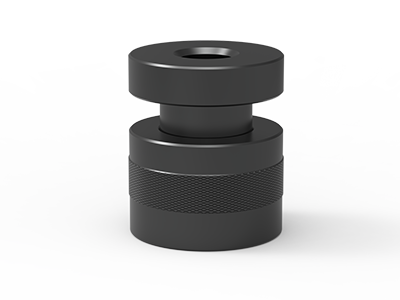 Screw Support Ø 80
 Shipping Bracket
 Tool Cart
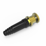 Ground Connection
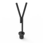 Welding torch holder
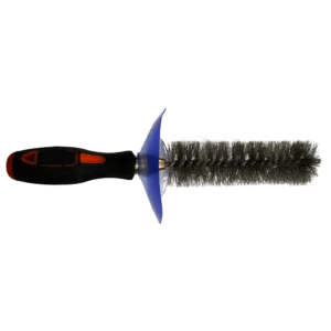 Brush with protecting cover
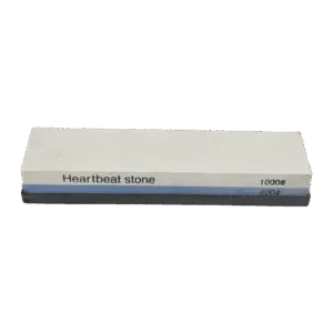 Oilstone
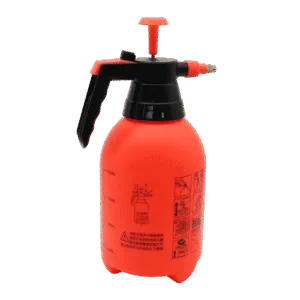 Pump Spray Bottle
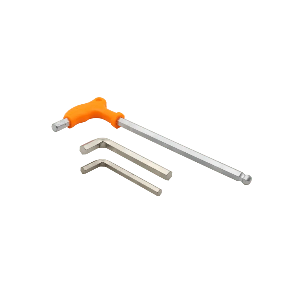 Allen Wrench
3D Welding Table Side Holes: When Are They Worth Specifying?
Specify side holes on a 3D welding table when a real fixture needs a mounting face below or beside the worktop: for an upright locator, an edge clamp, or a supported extension. If all your parts lie flat and top-hole tooling can reach every required datum and clamp point, side holes may add little value to that job. The deciding evidence is a fixture sketch showing workpiece position, tool access, load path and the exact side-face hole drawing—not a general claim that more holes are always better.
For an overseas buyer, the question is also commercial. A table with side-face holes may still arrive without the squares, bolts, supports or leg arrangement needed to use them. This guide turns a part drawing into a purchase specification that a supplier can check before a quotation is accepted.
What 3D welding table side holes actually change
A modular welding table uses its top holes to locate and fasten tooling across a horizontal plane. Holes in the table’s side faces offer another mounting plane at the perimeter. They can let an accessory project upward, outward or downward from the edge, subject to the particular table and accessory design. They do not increase the usable tabletop area by themselves, and they do not establish the load rating of a cantilevered assembly.
NewWeldTable’s TA282010N D28 table is listed with a 2,000 × 1,000 mm worktop, a 100 × 100 mm grid, Q355B steel construction, nitriding and oxidation treatment, and D28 holes on the top and side faces. Those published details are useful for a first layout. Ask for the current drawing of the quoted configuration before assuming that a particular side row, corner or bolt position is available.
The distinction matters most when the part occupies the worktop edge. A side-mounted fixture can keep a top hole free for another tool, or move a clamp body away from the weld. It can also make the edge harder to reach or create a projection into an operator aisle. Both effects should appear on the same layout.
Three jobs that can justify side holes
1. Locating a tall face above the worktop
A machine guard, cabinet frame or upright bracket may need a reference face at a height that a low stop cannot provide. An angle or square mounted at the table edge can bring a locating surface alongside the workpiece. Mark the actual contact height on the drawing. A tall square that touches only a small edge of the part is not automatically a better locator than a shorter, well-placed tool.
Check that the upright tool does not block the weld seam, tack sequence, inspection access or removal path. Show where a clamp presses the part into the reference; the square supplies a location, while the clamp and fasteners must secure the setup. For a tall or off-centre workpiece, ask the supplier to review the complete fixture and support arrangement rather than selecting a square from its height alone.
2. Clamping at an edge without covering the top
When a plate or frame sits near the perimeter, a side-mounted clamp or stop may leave more of the top surface open. This can help where a top-mounted clamp body would interfere with a torch, a locating pin or a second component. It is useful only if the side tool’s reach and direction match the required contact point.
Sketch the clamp in both its open and closed positions. Include handle travel, bolt installation access and the space needed to remove the welded part. A side hole directly opposite the intended clamp may still be unusable if a leg, under-table rib, workpiece overhang or adjacent tool obstructs it. Ask for underside and side elevations when the catalog image shows only the top.
3. Building an extension or a second fixture plane
Side holes can be used to fasten a modular extension or a raised fixture element. For example, NewWeldTable describes its UF281000 D28 U-shaped square as suitable for vertical setups and table connections. Its product information says an extension exceeding 1,000 mm needs a supporting table leg. Treat that as a warning to confirm the support arrangement for your exact assembly, not as a universal safe length for every table or load.
For an extension, document the projected length, workpiece weight and location, number of connection points, support position and planned lifting or loading method. Request an assembly drawing that shows the bolts and the extension support. A side connection should not be specified from a plan view alone: the vertical load path and stability are visible in elevation.
Choose the mounting plane from the workpiece, not the catalog
| Fixture need | Start with | Side-hole question |
|---|---|---|
| Flat plate with accessible top datums | Top holes and low stops | Would a side tool clear a top-hole conflict, or only add complexity? |
| Upright frame or box corner | Top holes plus a square | Does an edge-mounted upright give the required contact height and release path? |
| Part overhangs the table | Workpiece support plan | Where does the overhang load go, and is a separate support required? |
| Two connected tables or an extension | Assembly and support drawing | Which side rows, connection bolts and legs are required? |
Use this table as a decision prompt, not a design approval. If the workpiece is loaded from a crane or forklift, include the approach path and temporary set-down position. A fixture that is convenient after clamping may be unsafe or slow to load. Similarly, a corner stop that is perfect for the first tack may prevent the completed assembly from leaving the table.
Read the side-hole drawing before buying tooling
“D28” identifies the nominal hole system; it is not a complete connection drawing. Ask for the position and count of side-face holes on each face, row heights relative to the top surface, pitch along the edge, distances from corners, edge clearances and any interrupted areas. Verify which faces have holes on the exact model. A table can have a top grid without matching rows on every side.
Then match the accessory’s mounting pattern to those positions. A square may require two holes at a specific spacing; a clamp might use a single hole but need rotation clearance. Confirm the bolt type, actual engagement range, accessory thickness at the connection and the clearance behind the side wall. The D28 bolt selection guide covers the stack and engagement checks in more detail. For a mixed-brand installation, request both manufacturers’ drawings and a sample-fit check rather than assuming interchangeability from the nominal diameter.
- Coordinates: identify side, row and hole numbers on a dimensioned table drawing.
- Tool footprint: mark every accessory base and its required bolt holes.
- Clearance: show clamp travel, handle swing, leg locations and underside structure.
- Contact: dimension the point where the tool touches the workpiece, including height above the top.
- Support: show how an upright or extension is restrained and where its load is carried.
A 100 × 100 mm top grid on one table does not prove that the side holes have the same pattern or that their first hole sits at a convenient offset from the corner. Ask the supplier to dimension the side pattern rather than extrapolating it from the top view. This small drawing request can prevent an expensive tooling order that cannot be assembled as planned.
Plan the weld sequence around the side fixture
Side-mounted tooling changes where hands, torch, leads and inspection tools can reach. Mark the seam positions and initial tack order on the sketch. Check whether a clamp can stay in place for the weld or must be moved after tacking. If removal is necessary, make sure the remaining locators and clamps still hold the part as intended. Do not rely on a side square alone to restrain a workpiece during a process that may move it.
Leave access for cleaning spatter from the top and side holes. A bolt that fits a clean bore during trial assembly may be difficult to insert after the edge has accumulated debris. Also check how operators will verify the finished part: if a weld or clamp blocks a dimensioning point, plan a separate inspection setup. The table is a fixture platform, not a substitute for the part drawing or inspection plan.
Record successful setups by table model, hole coordinates, accessory SKUs and orientation. Photos help, but a photo alone often hides which side row or bolt length was used. A short setup sheet is especially valuable when several shifts rebuild the same vertical fixture.
What to put on the purchase order
Send one representative workpiece drawing and a simple top and side fixture sketch with your request. State the maximum workpiece envelope and weight for the proposed job, the material and weld locations, and how the assembly is loaded. Identify whether you need top-only tooling, side-mounted tooling, an extension, or a connected-table arrangement. If the fixture must handle several products, identify the largest and most awkward one rather than only the average part.
Ask the supplier to return a line-by-line list: table model and size; top and side-hole drawings; table material and surface treatment; each square, stop, clamp, support and bolt SKU; quantities; mounting locations; and any required leg or extension support. Confirm which accessories are included in the quotation. The site’s table and tooling packages are configurable examples, so their images should not be treated as a fixed bill of materials.
If you have an existing table, include its maker, model, measured hole and side-face geometry, plus photos of the relevant edge. If you are ordering a new table, ask for a dimensioned approval drawing before production and verify the side-hole layout against your fixture sketch. These steps are more useful than ordering a generic “full D28 accessory set” without the workpiece and mounting plan.
Make the side holes earn their place
Side holes are valuable when they solve a documented access, locating or extension problem. Their value depends on the specific table geometry, compatible tooling and supported load path. Start with one real fixture, draw the part and tools in top and side views, and resolve every connection before specifying the table.
Send your workpiece drawing, proposed table size, side-fixture sketch and destination country through the request a quote form. Ask for the side-hole drawing and an itemized table, tooling and support proposal so your workshop can check the assembly before ordering.