
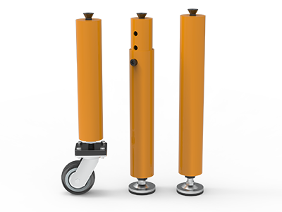
 Round Table Legs
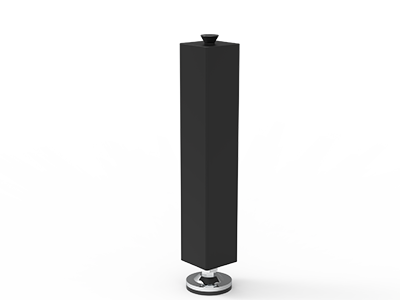 Square Table Legs
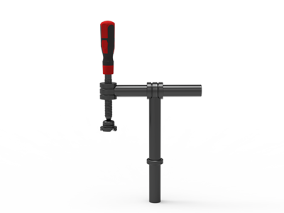 Clamp 180°
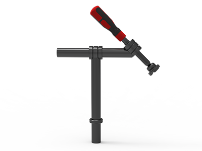 Clamps 45°
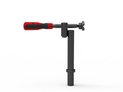 clamp 90°
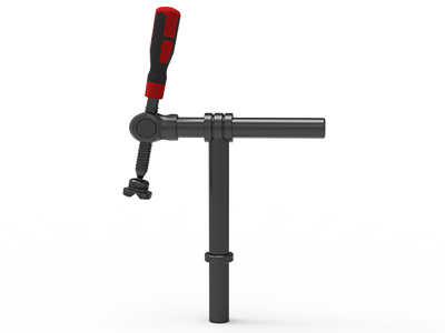 DRINK
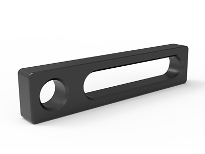 Stop
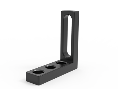 Angle Stop
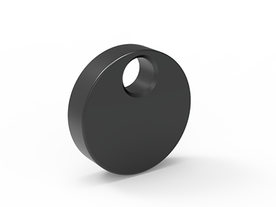 Eccentric Stop Ø 60
 Angle Alignment Template
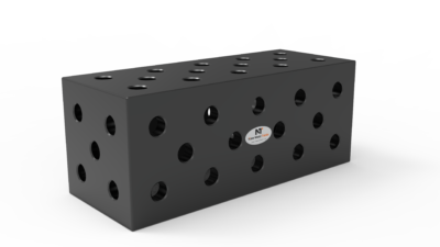 Square u-shape
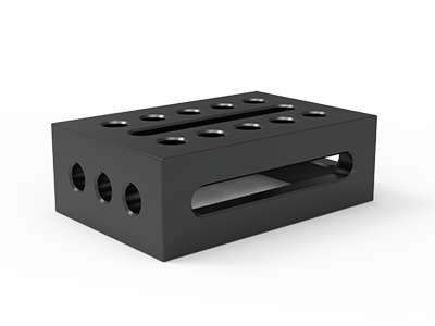 Support and clamping frame
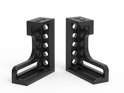 Angle support
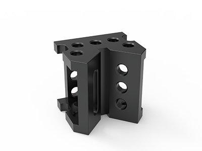 Corner Connection
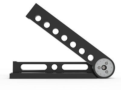 Universal angle clamping
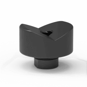 Prism with screwed-in collar
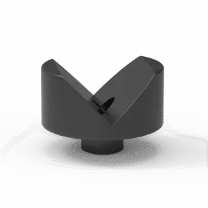 Prism with screwed-in collar
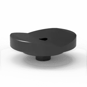 Prism with screwed-in collar
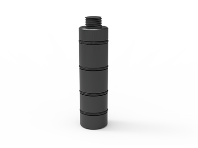 Prism Extension
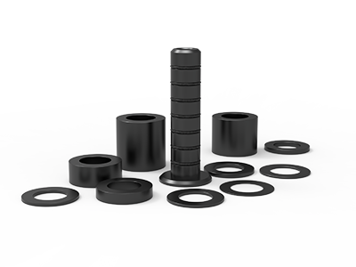 Set of Supports 11-piece set
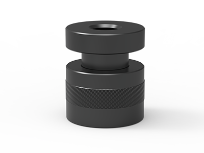 Screw Support Ø 80
 Shipping Bracket
 Tool Cart
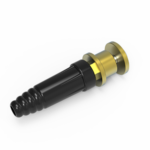 Ground Connection
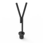 Welding torch holder
 Brush with protecting cover
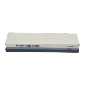 Oilstone
 Pump Spray Bottle
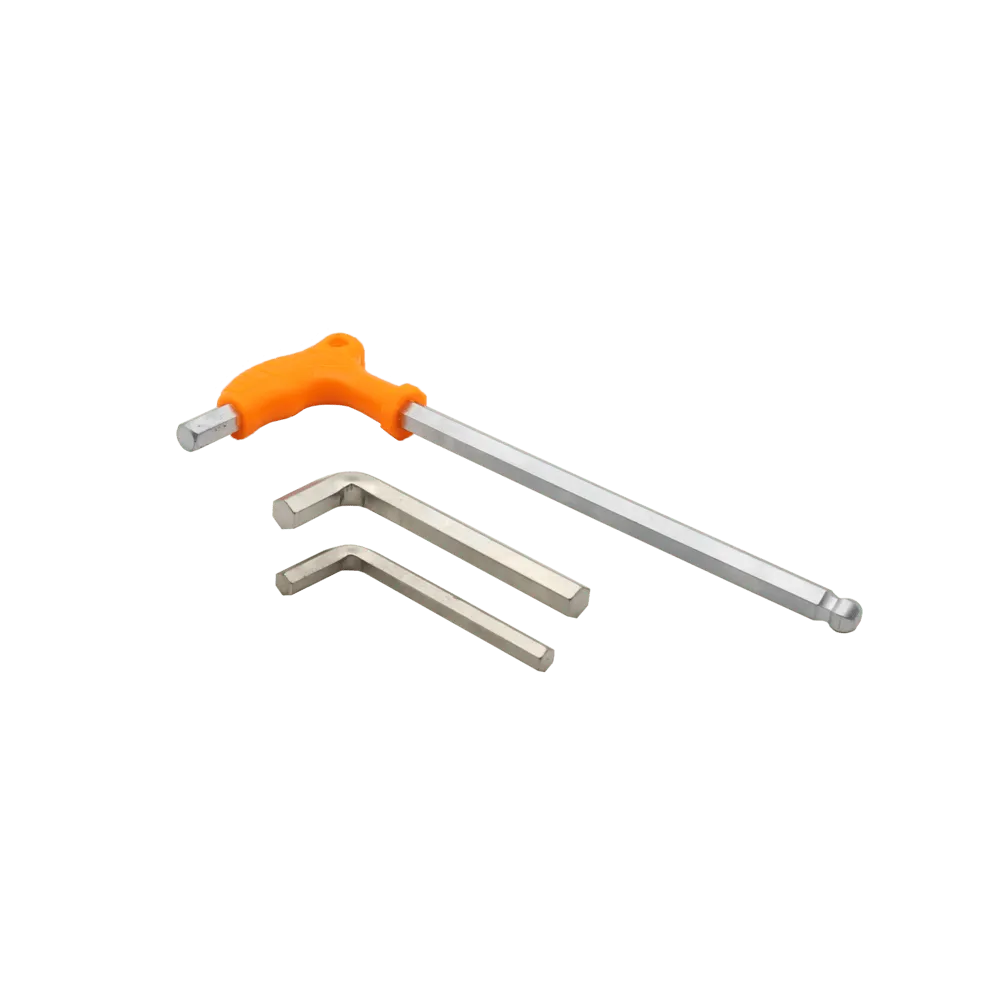 Allen Wrench
Welding Tables for Machinery Frames
Keep frame positioning repeatable.
Build a fixture plan around repeat parts, critical interfaces and practical operator access.
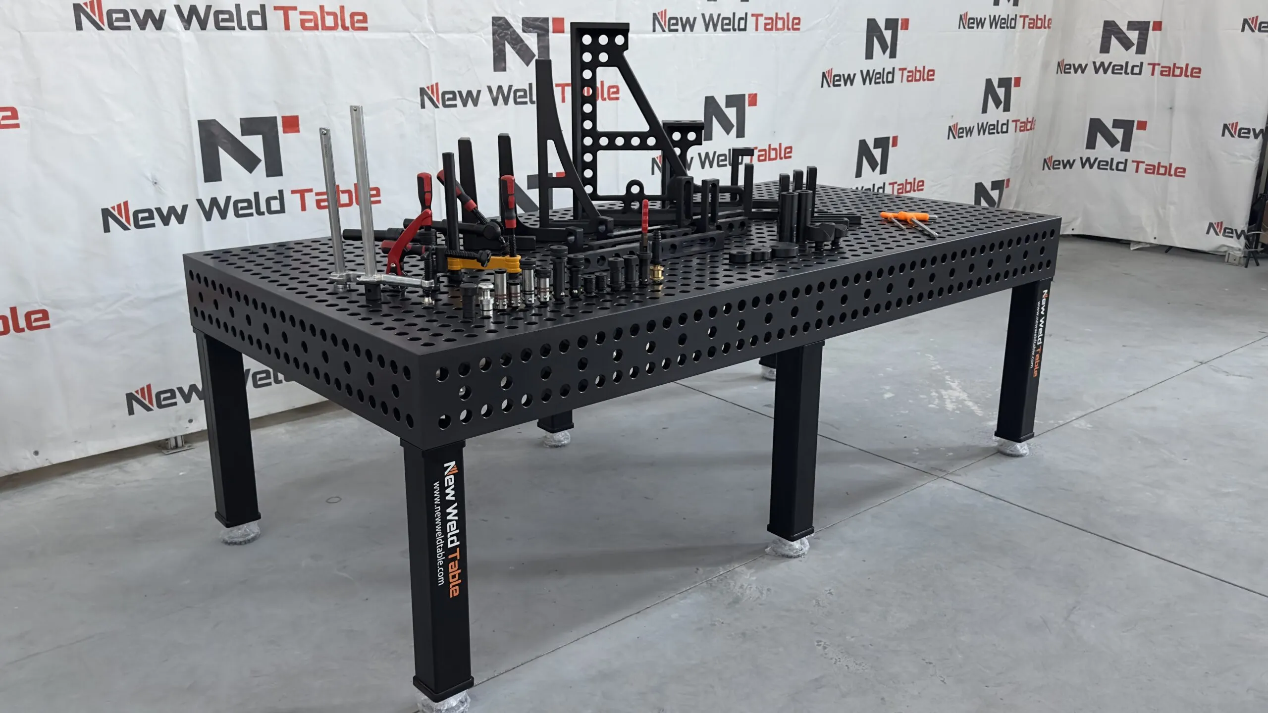
Plan around the workpiece
Equipment bases and machine frames often combine rectangular tubes, plates, brackets and mounting interfaces. A useful setup starts with the drawing: identify the locating surfaces, the dimensions checked after welding and which parts change between variants.
What the setup needs to solve
- Locate from the drawing
- Support the component
- Plan each variant
- Inspect the real result
The photograph illustrates a setup approach. Your table and tooling arrangement will be reviewed against your own drawings.
Details that change the configuration
Locate from the drawing
Choose references that match the inspection plan. Avoid letting non-critical cut edges determine important mounting positions.
Support the component
Position rests and stops so parts sit consistently before clamps are tightened. Check access beneath brackets and inside corners.
Plan each variant
Separate common locating elements from those that move between part sizes. Record fixture positions for the next batch.
Inspect the real result
Agree when dimensions will be measured, including any checks after unclamping. A fixture alone cannot guarantee the finished frame tolerance.
From drawing to a working layout
-
Share representative parts
Provide one drawing for each important frame family and mark critical interfaces.
-
Plan locating and access
Review stops, squares, supports and clamps together with weld access.
-
Record the setup
Document fixture positions and part references so the arrangement can be reproduced.
-
Review the first assembly
Check agreed dimensions and adjust the process before repeating the batch.
Send these details with your enquiry
| Item | What to include |
|---|---|
| Part family | Envelope of smallest and largest frames and the number of variants |
| Critical features | Mounting faces, holes and dimensions used in final inspection |
| Production | Batch size, changeover frequency and handling method |
| Existing tools | Hole diameter, grid, pin engagement and clamp details |
Questions before you order
Can the same table support different frame sizes?
A modular arrangement can be reconfigured within the table and tooling limits. Share the smallest and largest frames to check coverage and access.
Can you work with our existing fixtures?
Send their drawings or measured dimensions. Hole diameter alone is not enough to confirm pin fit, clamping range or interchangeability.
Let us review your application.
Send your drawings, workpiece details and delivery country. We will use them to discuss a suitable table and fixture configuration.