
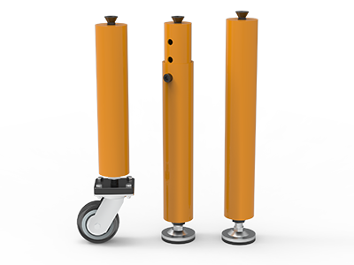
 Round Table Legs
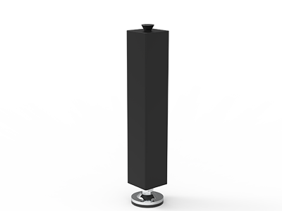 Square Table Legs
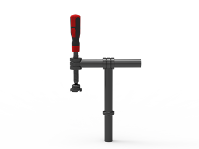 Clamp 180°
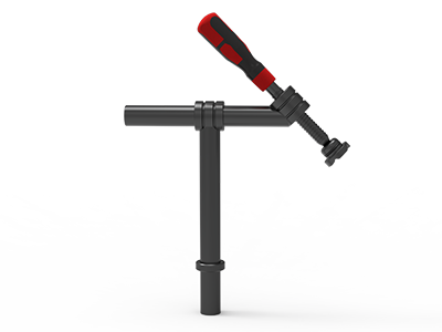 Clamps 45°
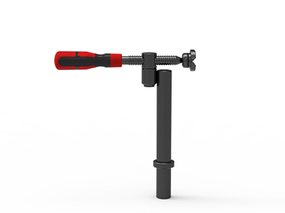 clamp 90°
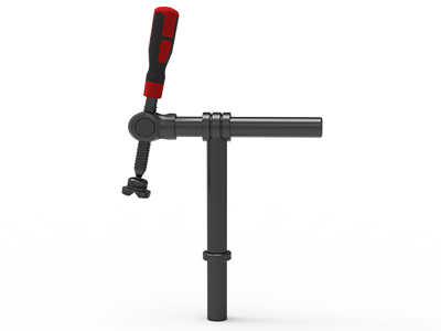 DRINK
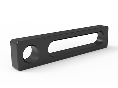 Stop
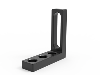 Angle Stop
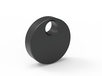 Eccentric Stop Ø 60
 Angle Alignment Template
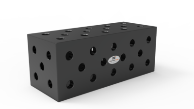 Square u-shape
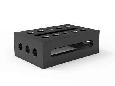 Support and clamping frame
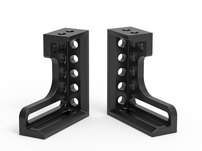 Angle support
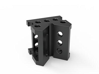 Corner Connection
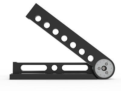 Universal angle clamping
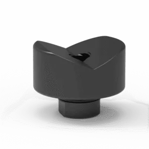 Prism with screwed-in collar
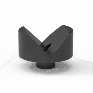 Prism with screwed-in collar
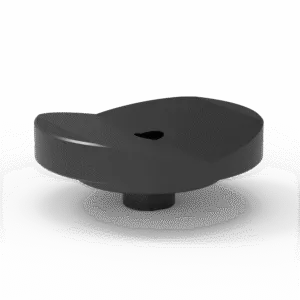 Prism with screwed-in collar
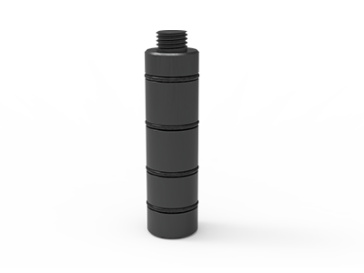 Prism Extension
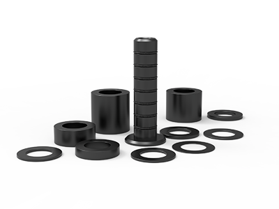 Set of Supports 11-piece set
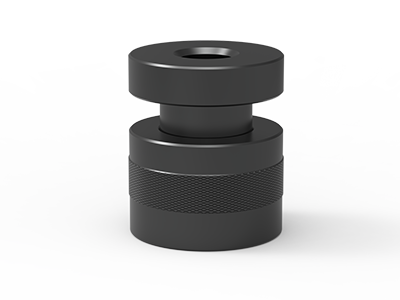 Screw Support Ø 80
 Shipping Bracket
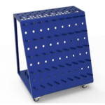 Tool Cart
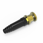 Ground Connection
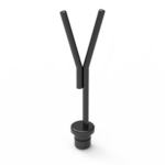 Welding torch holder
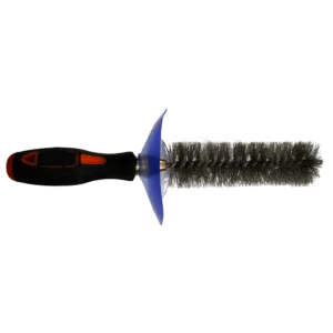 Brush with protecting cover
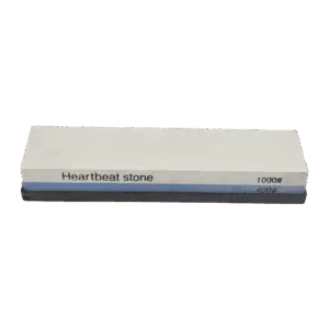 Oilstone
 Pump Spray Bottle
 Allen Wrench
D28 Welding Table Supports: How to Set and Check Fixture Height
Choose D28 welding table supports by the height each contact point must reach, the shape of the surface it touches, and the space needed to weld and remove the part. For a stepped weldment, a fixed-height support set can establish several known levels; a screw support is useful where the final contact height needs adjustment. Neither choice replaces a drawing-based check of the whole fixture, including the table, mounting hardware, part weight and weld access.
The common buying mistake is to ask for “some supports” without showing which faces need support. A supplier can then quote a kit that fits the D28 holes but cannot reach a recessed beam, clear a weld or support the assembly during loading. The method below turns a part drawing into a support schedule that a fabricator and a supplier can both check.
Start with the part, not the accessory height
Put the weldment drawing beside the table drawing. Mark the surfaces that can actually bear on a support: a sound base plate, a tube wall close to a joint, or a specified machined face. Do not assume an open tube end, thin unsupported sheet or rough flame-cut edge will make a reliable contact. Mark the joint gaps and the faces that must remain available for tacks, welds, inspection and removal.
Then record the vertical distance from the tabletop to each proposed contact face in the intended loading position. Use the drawing’s actual elevations, including any base plates or section offsets. For a frame with two tube depths, there may be two support levels even if its top face appears flat. If the part is flipped between operations, make a separate sketch for each orientation.
- Locate: decide which faces or stops establish the part’s position.
- Support: place contacts under areas that need bearing during loading, tacking or welding.
- Clamp: show where force pushes the workpiece toward its intended location.
- Release: confirm that the part can be lifted or slid out after welding.
These are different jobs. A support under a beam does not hold the beam against a side stop; a clamp can also deflect a part if the underlying support is missing. For a repeat fixture, mark the contact points on a layout sheet rather than relying on an accessory list alone.
Choose between support sets and screw supports
NewWeldTable currently lists a D28 11-piece support set (TZ28001) for varying support-surface height, and a D28 Ø80 screw support (TG28001) for adjustable height. The listings describe different approaches, but a buyer should request the current dimensioned drawing and itemized contents before treating a catalog range as a guaranteed usable stack in a particular fixture.
| Need at the contact point | Starting option | Check before ordering |
|---|---|---|
| Several defined height steps | D28 support set | Available increments, stack method and positive location |
| Fine adjustment around one working level | D28 screw support | Working range, top contact and adjustment access |
| Round stock above the table | Support with suitable V contact | Prism interface, diameter fit and restraint against rolling |
| Large offset or outboard position | Engineered extension or separate support | Mounting, load path and supplier-approved capacity |
A fixed stack can be convenient when the same height returns on every job. An adjustable support can compensate for a small variation between parts or help establish a contact during setup. It should not be wound upward until it lifts the assembly away from its intended datums. Once the fixture is set, record the adjustment or use a physical reference so the next operator can reproduce it.
The listed screw support is described for a 75–110 mm adjustment range. The listed support set describes height compensation with individual pieces. Treat those figures as catalog information for the named products, not as permission to combine every component at any height or load. Ask how the parts lock together, whether an adapter is required, and what contact piece is supplied at the top.
Calculate the whole height stack
For each contact, write a simple stack equation: required contact elevation = mounting interface + support body or stack + top contact piece. Measure all terms from the same tabletop datum. A V block, pad or custom locating piece can add height even when the screw support itself is within its nominal travel. Conversely, a recess in a fixture plate can lower the effective top contact.
Use a dimensioned sketch rather than subtracting product names from the part height. The sketch should show the tabletop, hole position, bolt or locating post, each stacked element, final contact point and the lower face of the workpiece. If the table has a different hole pattern or tabletop thickness from a previous purchase, request a compatibility check. The TA283015N D28 table, for example, is listed with a 3000 × 1500 mm working surface and a 100 × 100 mm top-hole grid; that does not tell you the height of a particular support assembly.
Leave adjustment room in both directions
If an adjustable support is specified at its very top or bottom travel for the nominal part, there may be no room to accommodate normal drawing variation or actual fixture assembly. Ask the supplier to show the intended setting in the middle of its usable range where practical. Check the current product drawing for minimum engagement and locking requirements; do not infer them from the advertised overall range.
Plan for the surface that actually contacts the part
A flat pad under a rectangular tube, a V contact under round stock and a non-marring contact under a finished surface solve different problems. For round material, see the separate D28 prism selection guide. Specify the contact style in the support schedule and confirm its interface with the chosen base; a shared D28 table system does not prove every top piece fits every support.
Place contacts where they help the fixture
Support positions should follow the load path and the assembly sequence. A long tube may need a contact near each end and one near a heavy joint, but the correct count depends on its section, span, part weight and loading method. Ask the fixture designer to review any outboard or cantilevered contact. A tabletop hole is a mounting option, not a rated support point for every possible overhang.
Keep supports away from the immediate weld area when they would block the torch, collect spatter in a screw thread or prevent a clamp from being removed. Leave a practical path for a wrench or hand to reach any adjustment after the part is loaded. On a repeat job, label support positions on the setup sheet by grid coordinates or a simple sketch, then mark the intended top elevation at each position.
For a thin or irregular component, more contact points are not automatically better. If all supports are tightened hard against a part with real shape variation, they can force it into the fixture and hide the condition that quality control needs to see. Decide which contacts establish the height and which merely prevent sag or movement. Check the drawing tolerance and the approved welding procedure before using a support to “correct” a part.
Check fit, stability and workflow before the purchase order
Run a dry layout on paper or in CAD with the actual table hole coordinates. Confirm that each base can be mounted in the proposed location without colliding with a table rib, adjacent stop, bolt head or clamp. Check whether the support is held by a bolt, a post or another interface, and specify the correct fastener length for the real stack. Do not assume that an accessory sold for “D28” is interchangeable across brands or generations without drawings.
Ask how the assembly is loaded: lowered by crane, placed by hand, or slid in from an edge. Tall loose supports may be vulnerable during loading. Plan how an operator will see that every intended contact has seated before clamping, and how the part will be released after heat distortion or tack buildup. If the fixture is used for inspection, distinguish a locating contact from a measurement reference and document the inspection method separately.
- Confirm the D28 hole diameter, pitch, table model and mounting-face thickness from current drawings.
- Request drawings for the support body, top contact, attachment method and any extension.
- Give the supplier the workpiece mass and where it bears; request an approved load arrangement for the complete assembly.
- Check tool access, weld access, spatter exposure, release path and storage between jobs.
- For export, ask for a packing list that separates small support pieces and identifies each part number.
When the support schedule is complete, compare it with any proposed D28 kit. A kit may include some height-setting parts, but the quantity and usable configuration should be checked against the actual jobs. Turn that check into an itemized kit quotation.
What to send with a D28 support RFQ
Send one drawing or sketch per representative weldment. Highlight the intended loading orientation, proposed contact points and required contact elevations above the table. State whether each contact must be fixed, adjustable or compatible with a V block. Include the table model and hole layout, expected workpiece weight, number of fixtures running at once, material and finished-surface concerns, destination country and any packing requirements. A photo of an existing fixture can help, but dimensions should come from a drawing.
Ask the supplier to return an itemized support schedule: part number, quantity, height range or stack drawing, top-contact type, mounting fastener, compatibility notes and any items that are excluded. For an adjustable assembly, ask which setting is intended at the nominal part height. This lets your production team approve the fixture logic before purchasing and prevents a vague “fits D28” answer from standing in for a usable setup.
To price a support layout for your jobs, send NewWeldTable your table model and part drawing. We can review the requested contact heights and quote the relevant supports and mounting parts as an itemized list.