
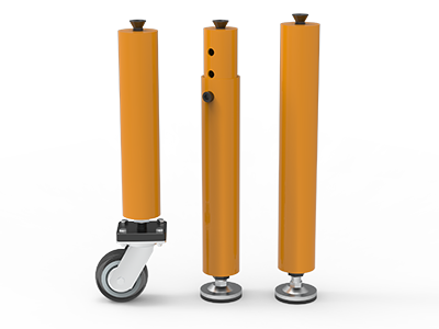
 Round Table Legs
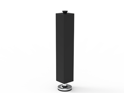 Square Table Legs
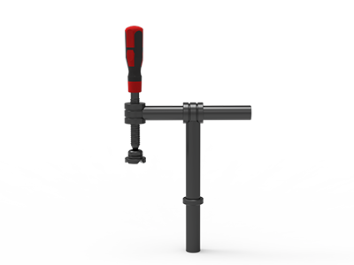 Clamp 180°
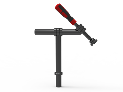 Clamps 45°
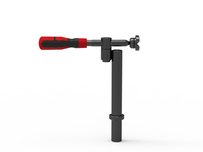 clamp 90°
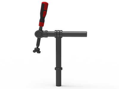 DRINK
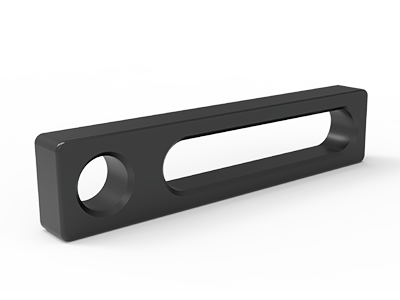 Stop
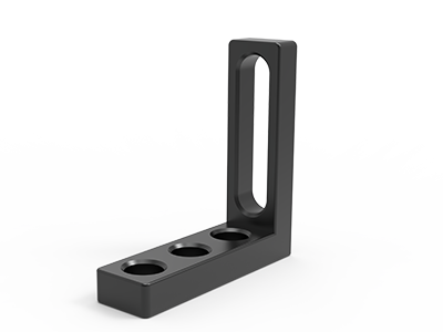 Angle Stop
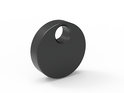 Eccentric Stop Ø 60
 Angle Alignment Template
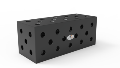 Square u-shape
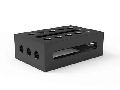 Support and clamping frame
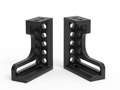 Angle support
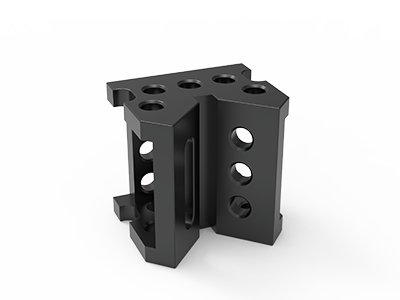 Corner Connection
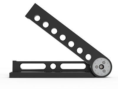 Universal angle clamping
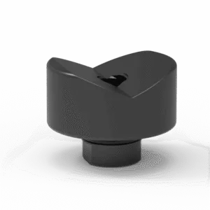 Prism with screwed-in collar
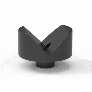 Prism with screwed-in collar
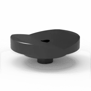 Prism with screwed-in collar
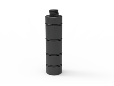 Prism Extension
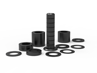 Set of Supports 11-piece set
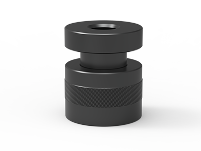 Screw Support Ø 80
 Shipping Bracket
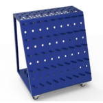 Tool Cart
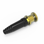 Ground Connection
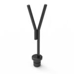 Welding torch holder
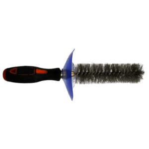 Brush with protecting cover
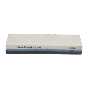 Oilstone
 Pump Spray Bottle
 Allen Wrench
D28 Welding Table Prisms: Choosing V Supports for Round Parts
Choose D28 welding table prisms by the round part you need to support, the contact geometry you can accept, and the space available for clamps and weld access. A V-shaped prism is a rest and locator; it does not replace a clamp, an axial stop, or a check of the finished assembly. Before buying, ask for the prism drawing and test the proposed position against your tube or shaft drawing. The angle in a product name describes the V geometry, not a guaranteed range of pipe diameters.
This guide is for fabrication buyers ordering fixtures for round tube frames, shafts, sleeves or short pipe assemblies on a D28 table. It covers the support decision and the information a supplier needs to quote a usable set. For a broader table configuration, see the TA282010N D28 table specification, which lists a 2,000 × 1,000 mm working surface and a 100 × 100 mm hole grid. Those dimensions are for that model; use your own table drawing if you run a different grid or surface.
What a welding table prism does
A prism has two faces that contact a round workpiece. Placed on a suitable fixture point, it gives a repeatable resting location while leaving much of the circumference accessible. Two supports can establish a working axis for a straight length; an end stop can establish the axial position. Clamps then keep the part seated during tacking and welding.
The support is only one part of the fixture. A tube can slide along its axis, rotate, lift when a clamp is opened, or move as welds are deposited. A round bar can also rock if the contact points are too close to one end. Plan the full restraint path on a drawing before selecting the V profile. If the part is thin wall or has a finished surface, discuss contact marks and pad material separately; the catalogue name alone cannot answer that question.
Compare the listed D28 prism geometries
NewWeldTable currently lists three D28 prism supports with screwed-in collars. The product names provide a nominal diameter notation and V angle, but the pages do not provide a verified minimum or maximum workpiece diameter. Do not read “Ø60,” “Ø80,” or “Ø120” as a pipe capacity. Request a dimensioned drawing showing the V opening, contact face width, collar, installed height and mounting interface before specifying a model for a particular tube.
| Listed model | Catalogue notation | Useful question for the drawing review |
|---|---|---|
| VX288090 | Ø80 × 90° | Does the steeper V place your part at the required axis height without interfering with the weld joint? |
| VX2860135 | Ø60 × 135° | Does the wider V give suitable face contact and enough clearance for your smaller round part? |
| VX28120157 | Ø120 × 157° | Does the shallow V support the proposed diameter without the part touching another feature first? |
These are selection questions, not performance ratings. The listed VX288090 90° prism, VX2860135 135° prism and VX28120157 157° prism are described as D28-compatible V-shaped supports for round workpieces. Their product pages do not publish a load rating, contact-pressure limit or diameter chart. Ask for those details if they affect your purchase.
Why V angle matters
For the same round diameter, changing the V angle changes the contact positions and the height of the round part’s center above the prism. That can alter whether a clamp reaches the part, whether a tack is accessible, and whether a second component lines up with the first. The angle also changes how easily a particular size can sit against both faces. The correct result depends on the actual prism dimensions, not the angle alone.
Make a simple section sketch through the part and support. Show the outside diameter at its specified maximum and minimum, the two intended contacts, the table top, the prism mounting position and the clamp pad. Repeat the check if one job uses several tube diameters. A support that looks suitable in a catalogue photo can leave a small tube too deep in the V or put a larger tube above the useful clamp reach.
Lay out the round part before counting supports
Start with the workpiece envelope: overall length, outside diameter, wall thickness or solid section, branch locations, flange locations and estimated mass. Mark where the finished part must be measured. Then place support points where they carry the assembly during the actual work sequence. Avoid putting a prism under a joint that must be welded all the way around unless the work can be safely repositioned.
Two supports for a straight piece
Two separated V supports are a practical starting layout for a straight tube or shaft. Their spacing must leave room for weld preparation and clamps while limiting unsupported overhang. The proper spacing cannot be selected from a generic rule because stiffness, length, added components and loading method all change the support demand. On a drawing, label each support by grid coordinate and show the distance from the nearest end and weld joint.
For a long or flexible assembly, review whether another support is needed, but first check that extra contacts will not force a bent or inconsistent tube into an artificial line. If the raw material is not straight, a fixture can locate selected datums without pretending to correct every section. Agree which dimension is controlled in the finished weldment. This is especially important for assemblies that receive a machined component or flange after welding.
One axial stop and controlled clamping
A pair of V rests helps define the transverse position. It does not define lengthwise position. Add an end stop where the drawing gives an axial datum, then check that the part can still be removed after welding. If the joint needs controlled axial movement for fit-up, make that adjustable in the setup plan rather than relying on friction at the V faces.
Choose clamp direction so the part seats into the supports without deforming the tube. A large screw clamp tightened hard over a thin wall can change roundness or joint fit. Specify a suitable contact pad and a shop-approved clamping procedure for delicate surfaces. The purpose is to hold the defined location through the planned operations; there is no useful universal clamping-force number for all tube sizes and materials.
Check the D28 interface and installed height
“D28” identifies the nominal table hole system. It does not prove that an existing bolt, collar and table from different suppliers will fit as a complete stack. Ask for the prism mounting detail and confirm the table hole drawing, edge clearance and any counterbore or shoulder. If a support is mounted on another riser, include every interface in the section view. A stack assembled from nominally matching parts may still put the workpiece centerline at the wrong height.
Compare the installed axis height with adjacent fixtures. A branch tube, flange or second shaft may need a different support level. The difference should be shown as a dimension on the fixture drawing and checked against the adjustability of the proposed supports. Do not assume the prism itself is height adjustable merely because its collar can be secured to a hole. If you need several heights, ask the supplier to identify the exact riser or support pieces and the resulting installed dimensions.
The TA282010N example has D28 holes on its worktop and side faces, a 100 × 100 mm grid, Q355B steel construction and nitriding plus oxidation treatment. Those specifications help plan where a prism can mount and how to record its coordinate. They do not establish the allowable load of a particular prism or an overhanging assembly. Confirm the capacity and support arrangement for the complete fixture if weight or offset loading is material to the job.
Plan access, welding sequence and inspection
A useful layout must survive more than the first tack. Sketch the torch approach to each joint, the clamp handle movement, and the path for lifting the assembly out. Leave space to clean the contact faces and remove spatter. If a prism lies directly under a circumferential joint, decide whether the part will be repositioned, rotated in an approved fixture, or welded in stages. A fixed V rest should not be treated as a turning roller.
Record the setup at the level your workshop can repeat: table model, hole coordinates, prism model, support height, end-stop position, clamp model and inspection points. For repeat jobs, mark the first-article dimensions to check after tacking and after welding. If the workpiece has a specified straightness, centerline or flange-face relationship, measure that requirement directly. The presence of a V support does not by itself establish dimensional conformance.
A practical prism RFQ checklist
A short, specific request is more useful than asking for “two D28 V blocks.” Send the drawing and a setup sketch, then request an itemized answer. The supplier should be able to identify what is included and which dimensions still require confirmation.
- Workpiece: outside diameter range with tolerance, length, wall thickness or solid section, material, approximate mass and any finished surface that must be protected.
- Operation: tack only, full welding, assembly or inspection; joint locations; required access and whether the part must be rotated.
- Location: required axis height, axial datum, support spacing, allowable overhang and the inspection dimensions on the weldment drawing.
- Table: model, D28 hole drawing, grid pitch, usable top area and any side-face mounting requirement.
- Tooling: preferred prism model or V angle, quantity, mounting collars or bolts, risers, clamps, pads and stops. Ask for a dimensioned assembled section.
- Commercial details: quantity, destination country and packing requirements for the complete tooling package.
Ask the supplier to show whether each proposed prism supports your smallest and largest specified outside diameters at the required axis height. Request the load information needed for your assembly and a sketch of any additional support for long or heavy workpieces. Confirm which items are included in the quote; otherwise a price for the prism alone may leave out the bolts, clamps and stops needed to run the fixture.
Which D28 welding table prism should you request?
Shortlist the V angles only after drawing the part at both diameter limits and checking the installed height. The 90°, 135° and 157° listings give useful starting options, but none of those names is a complete selection specification. For many buyers, the fastest path is to send one tube drawing and a table model, then request a section view and an itemized tooling list for the proposed layout.
Send your workpiece drawing, outside diameter range, table model and destination through our request a quote form. We can review the D28 prism choice alongside the required supports, clamps and mounting parts before preparing a configuration-specific quotation.